
Composite Mat Locking System Development & S7 Pin Redesign
Lightweight composite mats could slide apart under traffic. The locking system, and a later S7 pin redesign, had to make the roadway behave as one unit.
Engineering Case Study 008
- Industry
- Heavy-Duty Access / Ground Protection
- Product
- Interlocking Composite Access Mat System
- Role
- Product / Manufacturing Integration / Locking-Pin Redesign
- Engagement
- Field Performance Improvement, Production Integration & Component Redesign
- Primary Issues
- Mat movement under traffic; later failure of the original S7 locking pin
The Unrecognized Function of Weight
Conventional timber mats typically weighed approximately 1,800–2,000 lb dry and could reach 2,500–2,800 lb when wet. That mass quietly helped keep a timber roadway in place. The much lighter composite mat removed that passive restraint. On soft, wet ground, truck tires and heavy equipment could gradually slide individual mats apart, opening gaps, creating bumps and trip hazards, and allowing mud to pump onto the working surface.
Field experience established a new requirement: the installed roadway had to behave as a connected system rather than as a collection of individual mats.
Locking System Development
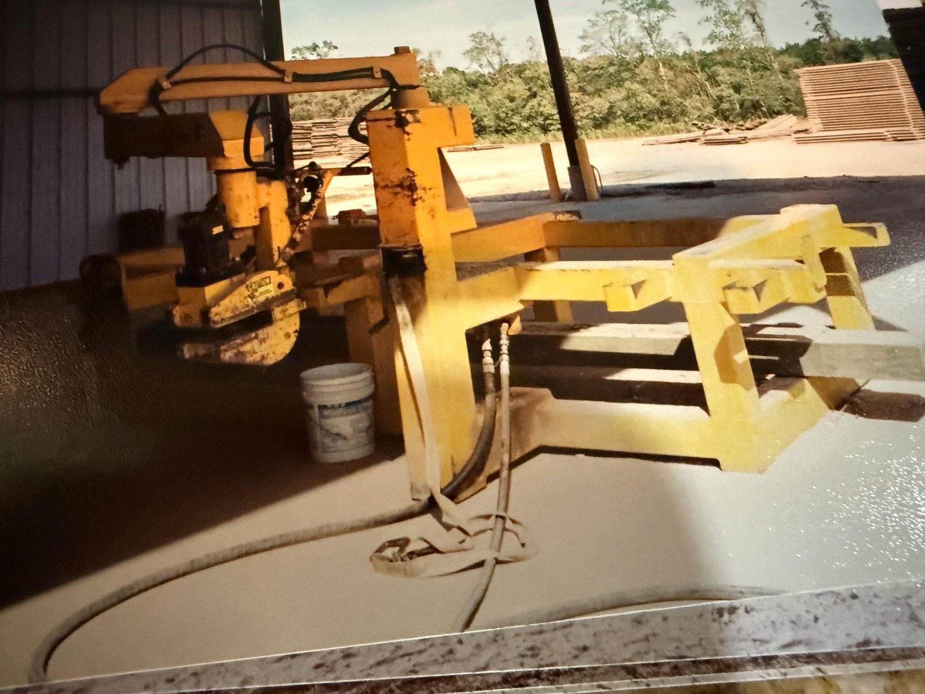
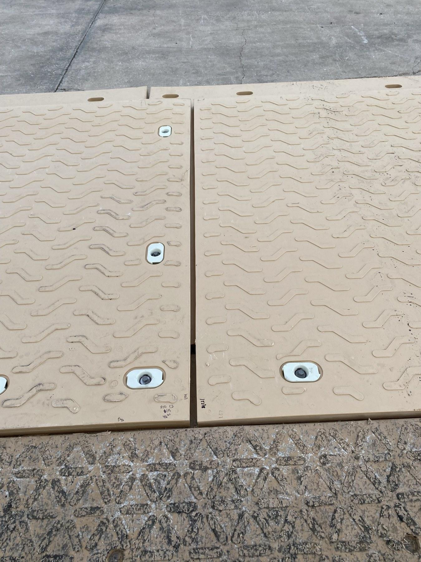
The connection had to install quickly, resist vertical and shear forces, tolerate dirt and mud, remain below the working surface, and survive years of field service. Early locking pockets were produced as a secondary operation with custom equipment. The manufacturing process was later improved by adding mold inserts so the recessed pockets were formed directly during molding.
Field Installation
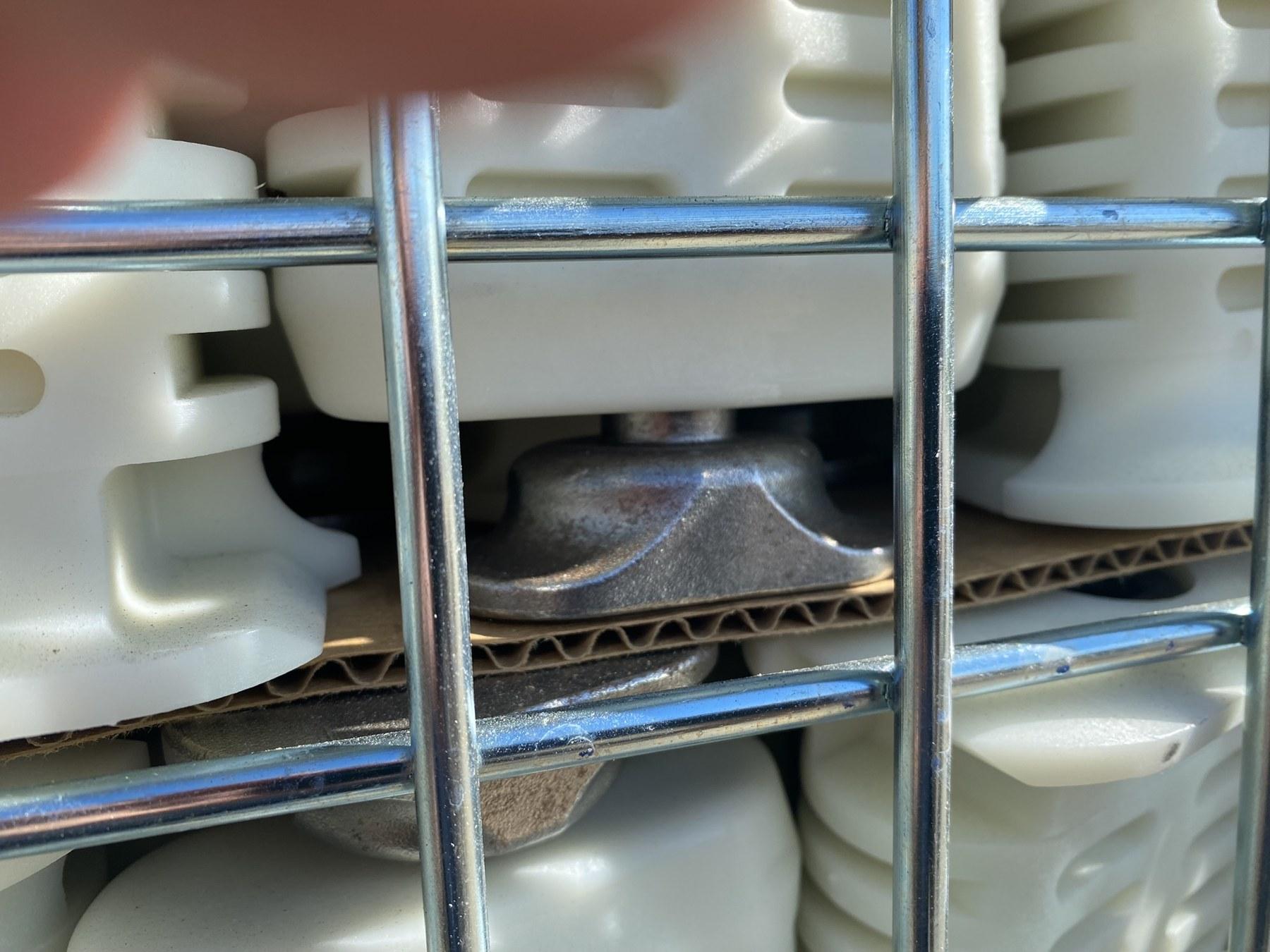
Pins were transported to the work area in metal baskets containing several hundred units. Personnel manually placed a pin into each recessed pocket and used a T-handle wrench to rotate the locking feature 90 degrees. Several purpose-built tools were developed over time to improve installation and removal.
A Second Engineering Problem — Failure of the Original S7 Pin
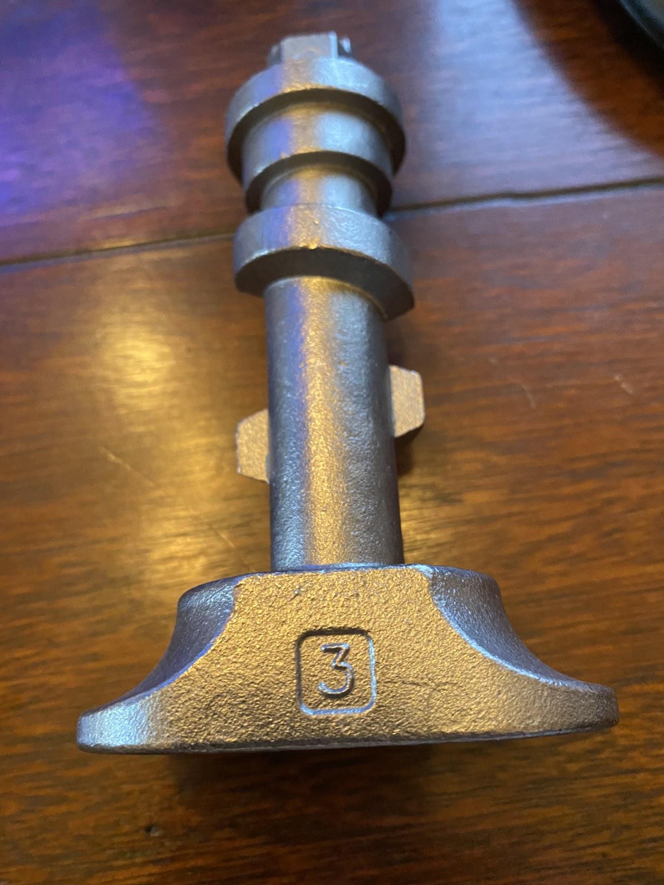
The locking system later presented a separate component-level problem. The original S7 pin failed in service, and I was asked to redesign it. The redesign had an additional functional requirement: as the core was rotated 90 degrees, the pin had to draw the connected components together by approximately 1/8 inch.
Redesign Concept
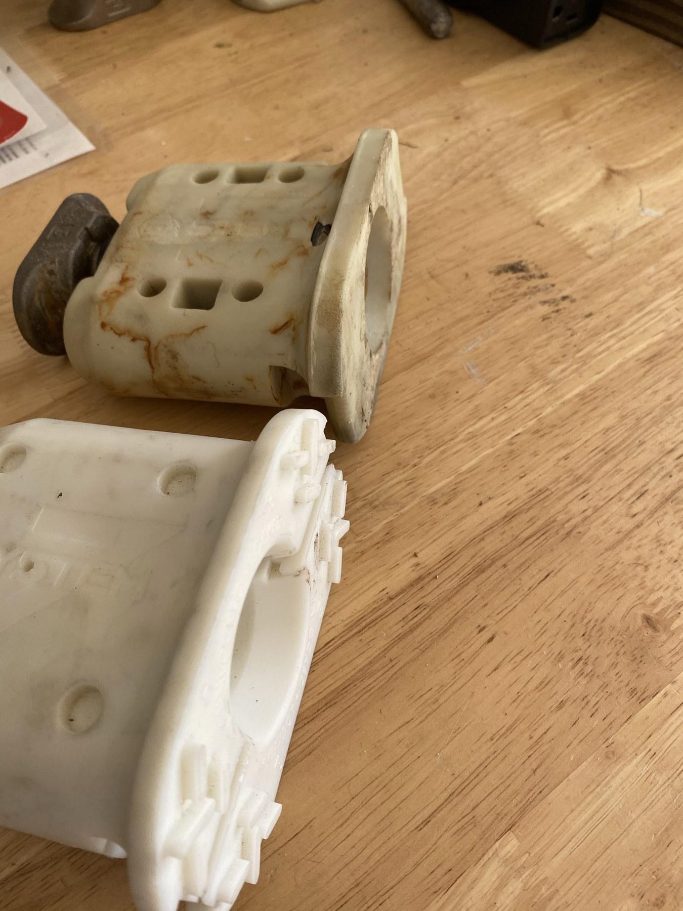
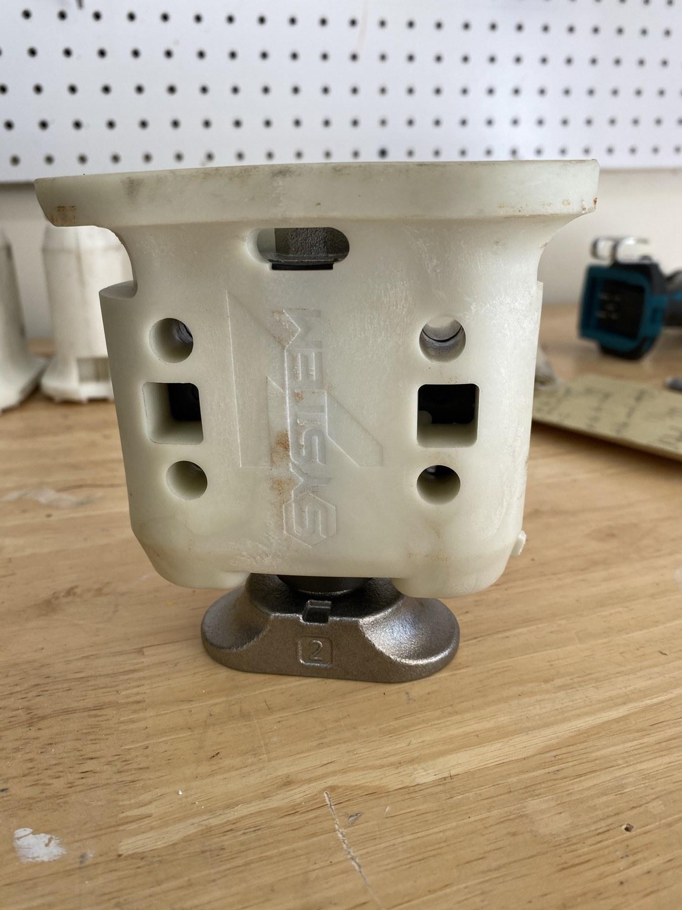
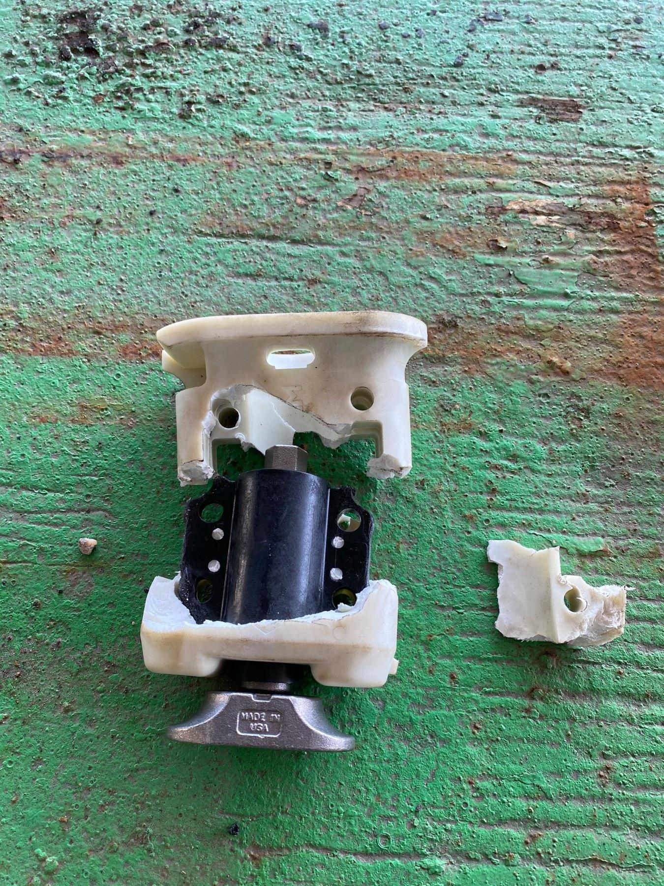
The revised design changed the internal locking mechanism rather than simply increasing the size of the original pin. The new version used the black inner core shown in the photographs. Its geometry converted the 90-degree rotation into both locking action and approximately 1/8 inch of draw-up, pulling the connection tight as the operator completed the quarter-turn.
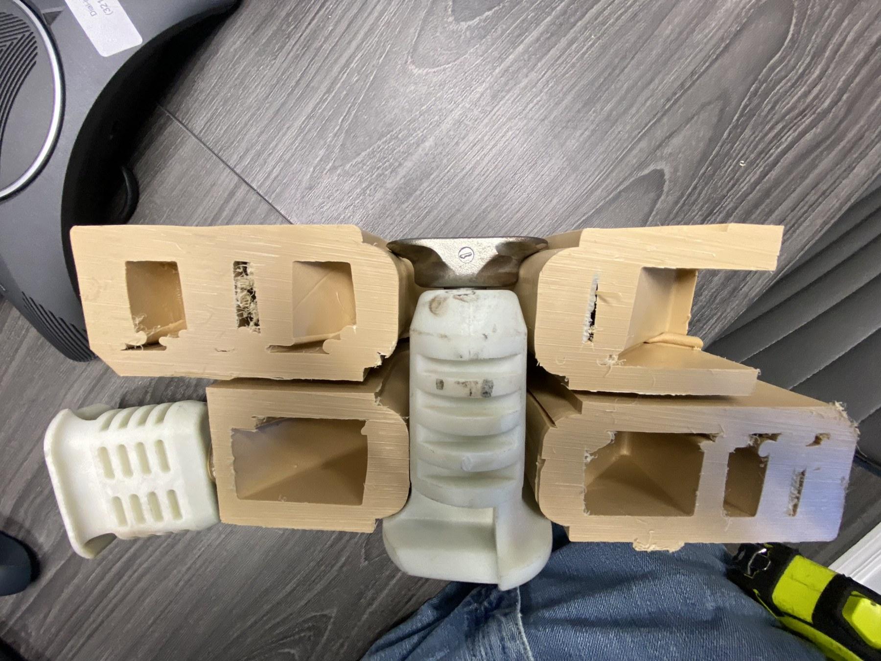
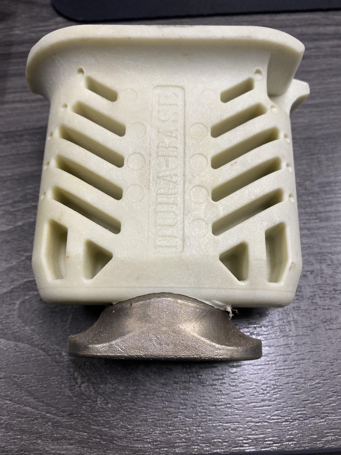
The redesign also had to remain compatible with the existing recessed pocket and the basic field installation method. This preserved the overall mat system while addressing the failure mechanism and adding a positive clamping function.
Destructive Validation
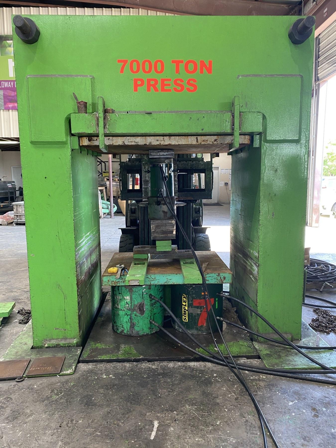
The redesigned pin was subjected to destructive testing rather than being accepted on geometry alone. Test fixtures were used to load the pin and pocket assembly until failure. The revised design outperformed every competing locking pin evaluated in the strength testing performed during the program.
Additional Development & Durability Work
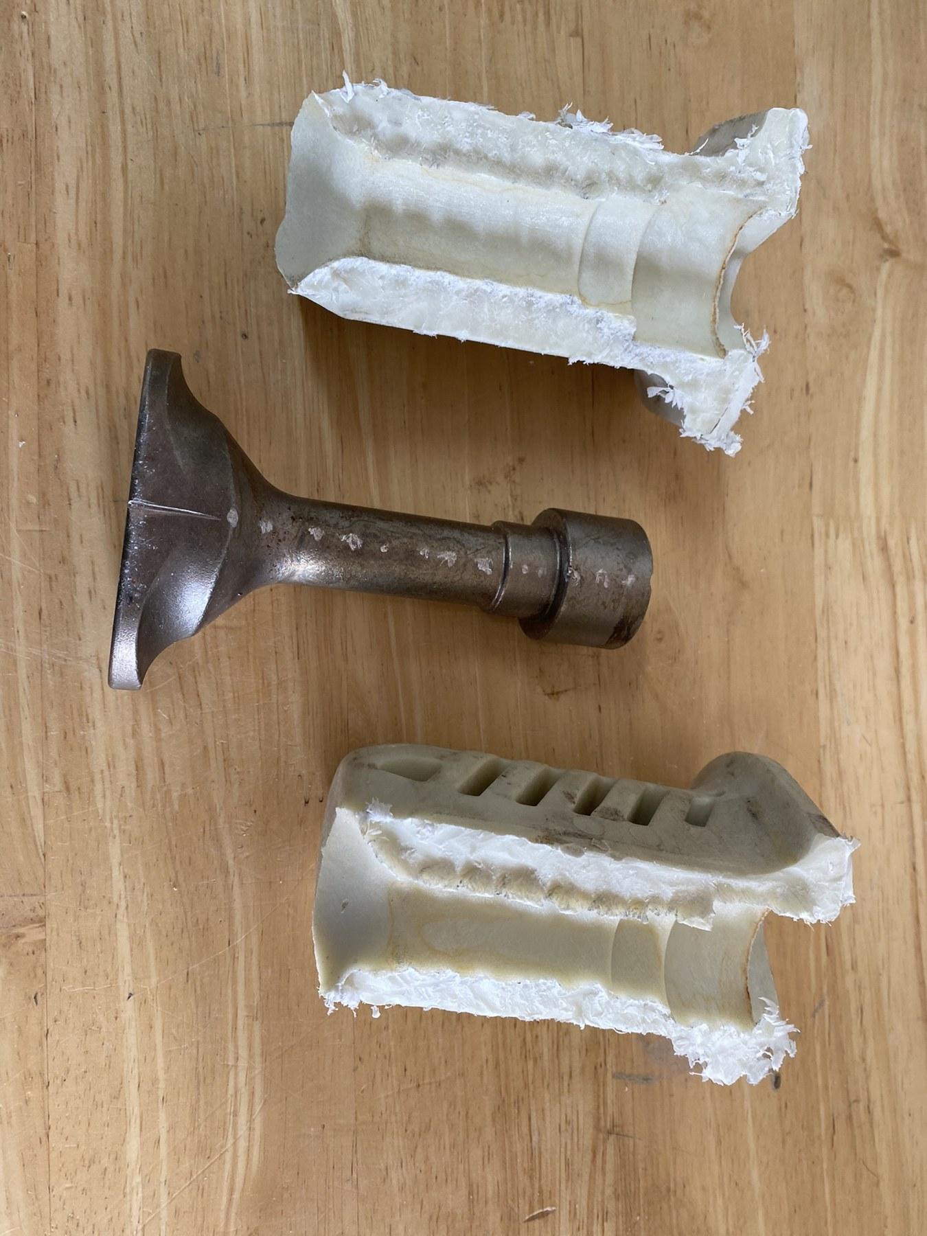
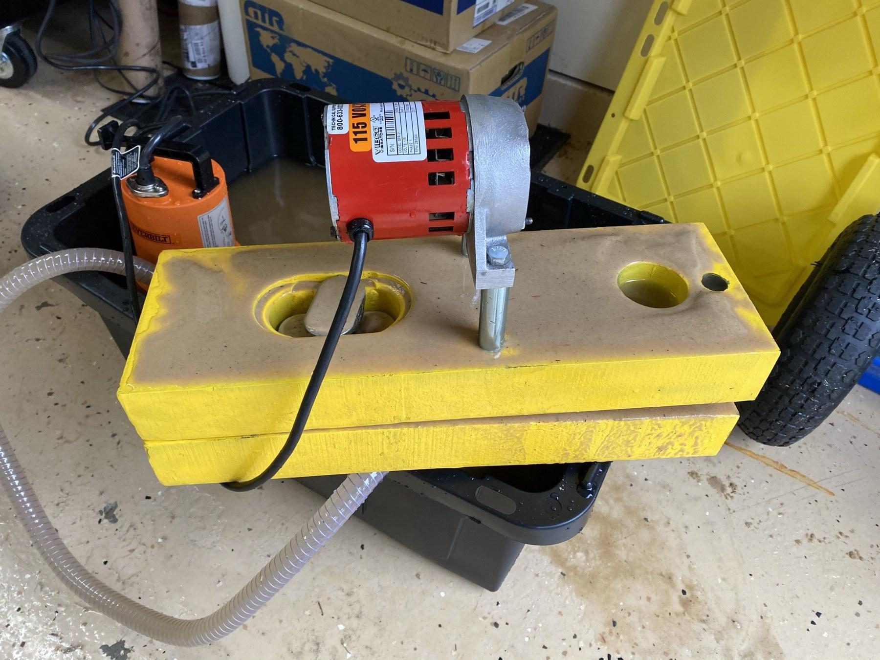
The development program also included additional fit, configuration and durability work. The photographs document multiple physical iterations, sectioned parts and test hardware used to understand how the lock carried load and how the polymer body interacted with the internal locking component.
Technical Success, Market Rejection
Technically, the redesigned pin achieved the engineering objectives. It corrected the original S7 failure, provided the specified 1/8-inch draw-up through a 90-degree core rotation, and produced the strongest performance of the locking pins evaluated in the program.
Commercially, however, the market did not accept the design. Installers were accustomed to existing pin behavior and operating conventions. Even though the revised pin performed better mechanically, it did not work exactly like the pins crews were used to using. The result was an important product-development lesson: superior mechanical performance does not automatically produce market adoption. Field familiarity, installation habits and user expectations can be design requirements just as real as strength and durability.
Results
| Area | Result |
|---|---|
| Original system problem | Lightweight composite mats could shift and separate under traffic. |
| System response | Mechanically connect mats so the installed roadway behaves as one unit. |
| Manufacturing improvement | Recessed pin pockets changed from a secondary operation to mold-formed features. |
| Original S7 problem | Original locking pin failed and required redesign. |
| New functional requirement | Approximately 1/8-in draw-up during a 90-degree rotation of the locking core. |
| Redesign | New internal locking geometry using the black inner core. |
| Validation | Destructive testing of physical pin/pocket assemblies. |
| Strength result | Revised design outperformed all competing pins evaluated in the program. |
| Commercial result | Market rejected the design because its operation differed from familiar field pins. |
| Engineering lesson | Technical superiority and user acceptance must both be designed into an industrial product. |
Engineering Significance
This case contains two distinct but connected engineering lessons. First, reducing the weight of the original timber product removed an unrecognized stabilizing function and forced development of a mechanical roadway connection. Second, when the original S7 pin later failed, the answer was not merely a stronger replacement. The redesign introduced a defined mechanical action — a quarter-turn lock that also drew the joint up approximately 1/8 inch — and was validated by destructive testing.
The revised pin demonstrated that a design can be technically superior and still fail commercially when it conflicts with established user behavior. For industrial product development, the operator and the work method are part of the system.